Introduction
Recently, I was working on a I2C driver for my ADXL sensor. I took the challenge of not using the HAL libraries but wrote the driver using just the CMSIS headers to understand the intricacies of the I2C protocol.
- The source code can be found here: Github Repository
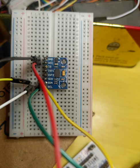
ADXL Accelerometer
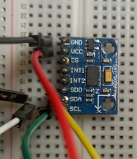
The pinout used for the sensor is as follows:
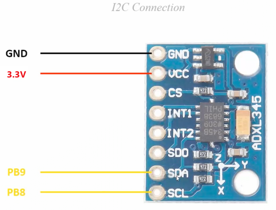
The axes of the sensor are indicated on the top of the sensor.
I2C Protocol
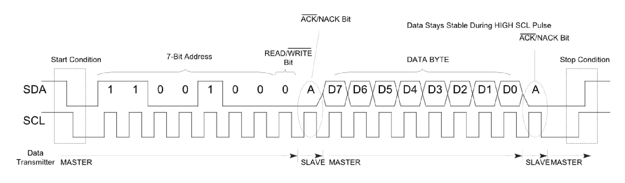
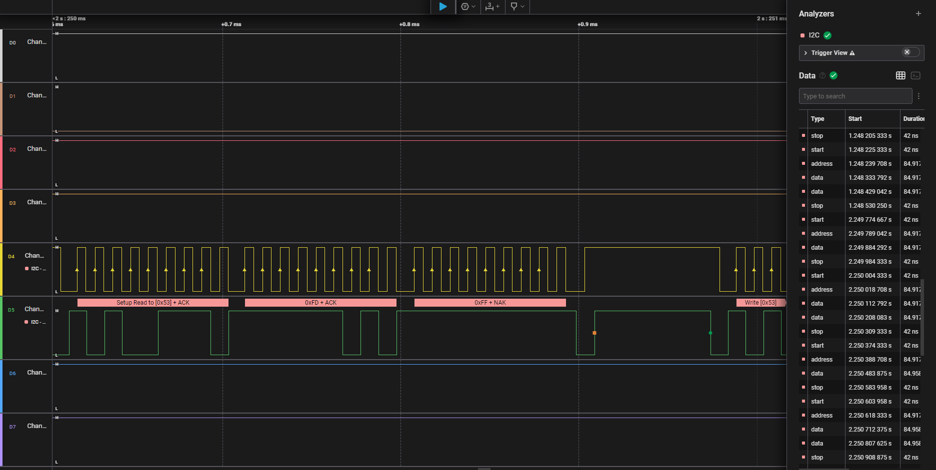
Analyzing Signals
In this section I will showcase the lines of code and the corresponding signals which relate to the I2C protocol
1. I2C Initialization and Scan
First the STM32 board initializes the I2C interface and performs and I2C scan
// enable I2C
I2C1_init();
I2C1_scan_bus();
2. ADXL Initialization
The procedure adxl_init() performs several steps to configure the registers of the accelerometer and verify if communication occurs properly. The detailed explanation for the I2C functions can be found in Core/Src/i2c.c.
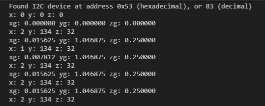
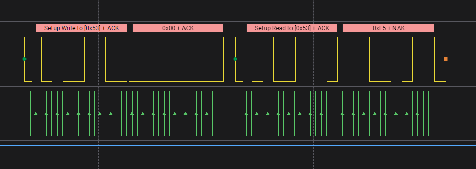
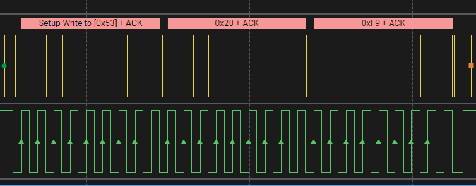
2.1. Get Device-ID
adxl_read_address(DEVID_R);
DEVID_R register holds a fixed device ID code of 0xE5. This confirms if the accelerometer is in correct state and the master can read from the slave.
Steps:
- Generate Start Pulse
- Transmit slave address + use write mode (
I2C1->DR = (saddr << 1) | 0) - Transmit memory address: (
I2C1->DR = maddr). Device ID is held at register0x00 - Generate Acknowledge Pulse
- Generate Restart Pulse
- Enter receive mode (
I2C1->DR = (saddr << 1) | 1) - Read data from the memory address (
*data = I2C1->DR). The device ID is0xE5as expected - Generate NAK Pulse indicating end of communication
- Generate Stop Pulse
2.2. Set Data Format Range
We will use ±4g range for the accelerometer.
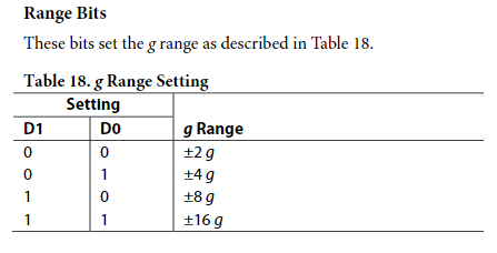
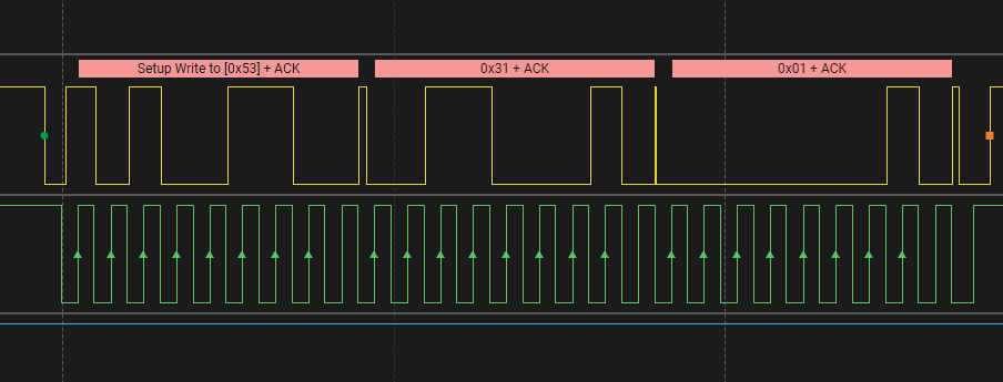
adxl_write(DATA_FORMAT_R, DATA_FORMAT_FOUR_G); // reg: 0x31, value: 0x01
2.3. Set Power Control to Measurement Mode
// configure power control measure bit to measurement mode
adxl_write(POWER_CTL_R, POWER_CTL_SET_MEASURE_B);
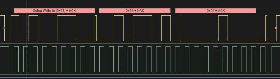
The actual register address is 0x2D and value is 0x08. However due misaligned clock / glitch the logic analyzer may have interpreted slightly incorrect values.
3. Calibration Sequence
We can calibrate the sensor and set the offset values from a reference measurement. I had used the position in which sensor was at rest which should give the values (0g, 0g, 1g). Accordingly, I calibrated the offsets
adxl_calibrate(0, 0, -7); // calibration value for 4g: (offset / 2)

void adxl_calibrate(int8_t x, int8_t y, int8_t z) {
    adxl_write(OFSX_R, x);
    adxl_write(OFSY_R, y);
    adxl_write(OFSZ_R, z);
}
X-Axis
Y-Axis
Z-Axis
4. Reading Values
void adxl_read_values(uint8_t reg) {
    I2C1_burstRead(DEVICE_ADDR, reg, DEVICE_DATA_READ_LEN, (char*) g_data_rec);
}

const double FOUR_G_SCALE = 128;
int16_t g_x, g_y, g_z;
double g_xg, g_yg, g_zg;

int main() {

	// ...

	while(1) {
		adxl_read_values(DATA_START_ADDR);

		// note: we cannot directly read the result into a float.
		// read into an int16_t to properly interpret the twos complement number
		// (float does not follow twos complement but IEEE754)
		g_x = (g_data_rec[1] << 8) | g_data_rec[0];
		g_y = (g_data_rec[3] << 8) | g_data_rec[2];
		g_z = (g_data_rec[5] << 8) | g_data_rec[4];

		g_xg = (g_x / FOUR_G_SCALE);
		g_yg = (g_y / FOUR_G_SCALE);
		g_zg = (g_z / FOUR_G_SCALE);

		printf("x: %d y: %d z: %d \n\r", g_x, g_y, g_z);
		printf("xg: %f yg: %f zg: %f \n\r", g_xg, g_yg, g_zg);

		systickDelayMs(500);
	}
}
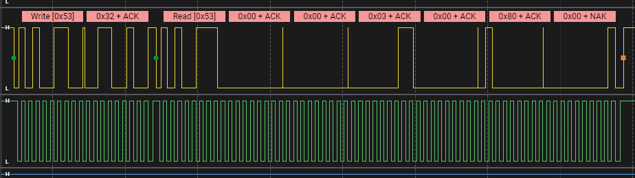
We read the 3 registers starting from address DATA_START_ADDR corresponding to X0 measurement. Then we combine the higher and lower order bits to get the raw values. Then we scale them according to our data range.
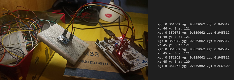
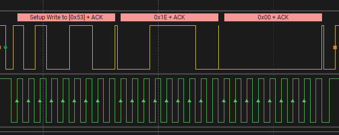
The below signals correspond to the hex form (00 00, 00 03, 00 80) according to the bitwise operations. This is equivalent to (0, 3, 128) as raw values. After scaling we get the results:
x: 0 y: 3 z: 128
xg: 0.000000 yg: 0.0234375 zg: 1.000000
Quiz
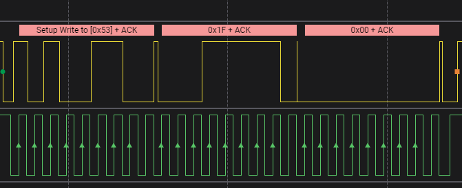
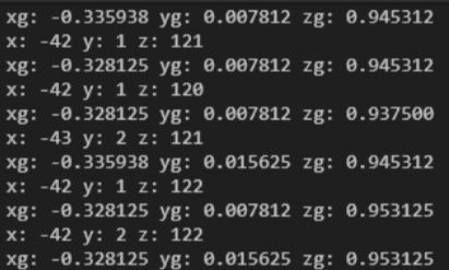
Another result you can try decoding is the following. Guess the orientation of the accelerometer (Hint use two’s complements for the numbers not unsigned integers.)
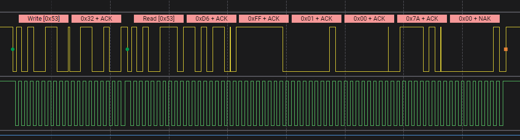
Answer
The sensor is leaning towards x-axis and has a lower component of z acceleration since it is inclined.
Values:
Results
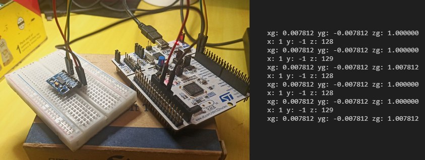
Z-Up
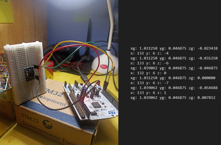
X-Up
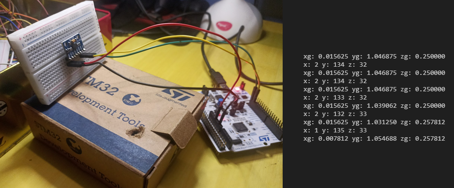
Y-Up
Slant Orientation